Abstract: Gamma correcTIon is used to correct for the nonlinear relaTIonship between luminance and brightness. This applicaTIon note presents an assembly program written for the MAXQ2000 microcontroller (µC) that uses gamma correcTIon with a fixed-frequency PWM signal to linearly increase and decrease the brightness of an LED. The PWM duty cycles, stored in a Lookup Table (LUT) located in Utility ROM memory, are gamma corrected to produce linear brightness changes. The software compiles using the free MAX-IDE development tool and runs on the MAXQ2000 evaluation kit .
BackgroundWhen an LED emits light, gamma correction is used to account for the power-law relationship between luminance and brightness. Although often used interchangeably, luminance and brightness are not synonyms.
Luminance: The emitted light, projected per unit area measured in cd / m² (candela / meter²).
Brightness: The perceived luminance attributed by the human eye.
The power-law relationship can be approximated by:

In this discussion, γ is equal to 2.5.
Controlling the LED IntensityAppendix A is an assembly program that linearly ramps-up and ramps-down the brightness of an LED. The intensity values have been gamma corrected to approximate a linear change in brightness.
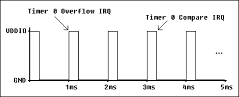
The LED is controlled using PWM. Timer 0 generates the PWM signal on P0.0 (visible on LED3 of U11 on the MAX2000 evaluation kit) and is set for 16-bit reload / compare timer mode. In this mode, Timer 0 generates two interrupt requests (IRQs): one on timer overflow, and one when the timer is equal to the compared value in T2C0. Figure 1 illustrates how this process creates a PWM signal. Note that the Overflow IRQ controls the PWM period, while the Compare IRQ controls the PWM duty cycle.

Figure 1. Using Timer 0 to generate a PWM signal.
Timer 1 is used to change Timer 0's PWM duty cycle, and, therefore, change the intensity of the LED. Every 50 milliseconds, Timer 1 generates an overflow IRQ that loads a new value from a lookup table (LUT) into the T2C0 register.
Calculating the gamma-corrected PWM duty cycles was done using equation 2, where: T2C0γ = gamma-corrected compare value for Timer 0 T2C0 = non-gamma-corrected compare value for Timer 0 γ = gamma-correcting factor (ie, 2.5) counts is the number of timer steps between reloads on Timer 0 (ie, 10000h-0C000h = 04000h) offset is the Timer 0 reload value (ie, 0C000h)

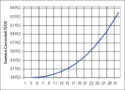
With a Timer 0 reload value of 0C000h, for example, 04000h timer steps occur between each reload. Assuming that 32 PWM duty cycles were used to increase the intensity of the LED and based on the LUT, the non-gamma-corrected compare values for Timer 0 (T2C0) would be: 0C000h 0C200h 0C400h ... 0FA00h 0FC00h 0FE00h The difference between each value is 0200h, or 04000h divided by 32. Using equation 2 to apply gamma correction to the values above, yields the following values for T2C0 ( Figure 2): 0C000h 0C002h 0C010h ... 0F209h 0F676h 0FB1Dh The source code in Appendix A adjusted these values slightly to eliminate timer problems. Timer 0, for example, does not stop when an IRQ occurs. Care must be taken, therefore, to ensure that the reload value is not close to the compare value (ie, T2C0-T2R0> some minimum positive value).

Figure 2. Gamma corrected T2C0.
Using Lookup Tables (LUTs) The PWM duty-cycle values mentioned previously are stored in a LUT in the MAXQ2000 microcontroller's program memory. While using program memory for constants and LUTs frees data memory, it does require longer access time.
The Utility ROM function, moveDP1, is used to retrieve data from program memory (see MAXQ Family User's Guide: MAXQ2000 Supplement). Note that because future revisions of the Utility ROM may not be at the same location in the MAXQ2000's ROM, the user should load the address of each function from the Utility ROM function table stored at address 0800Dh. Fortunately, this can be done during program initialization and the function addresses can be saved for use later in the program.
The source code in Appendix A loads the address of the moveDP1 Utility ROM function into the A [4] register, and uses this saved address to call the function.
ConclusionUsing LUTs to save the results of precomputed calculations can significantly increase firmware execution speed. If the LUT is saved in program memory, the MAXQ2000 Utility ROM functions quickly access the data. To further increase firmware execution speed, the MAXQ2000 can load the LUT data from program memory into SRAM at program initialization.
Download: Firmware and project files (ZIP, 18kB)
Appendix A. Assembly Source Code

Download Appendix A (PDF, 29.92kB)


